
Concept and diagram with Blender and Krita
Architectural diagrams are an important part of the design process. They are just as prevalent while studying as they are in the professional field through competitions, feasibility studies, and commissioned projects. Most students and professionals are likely well aware of how to produce diagrams with the software packages usually popular in universities and professionally, yet there is a great opportunity to learn how to make beautiful diagrams with free and open source software. We will be using Blender and Krita. If you are not familiar, Krita is an open source raster editing program aimed primarily at digital sketching and painting. Yet has many of the needed features for diagrams compared to Photoshop and Affinity Photo/Designer (expect more on Affinity soon) making it highly functional for architecture.
The Video

It is said that a picture is worth a thousand words, so then a video with 10,000 pictures must be priceless! Yes, indeed, yet it’s always great to have a good old-fashioned written guide with sticky points for the trickiest bits for reference purposes when you would like to revisit a specific topic. So this guide is supplementary to the video above
The Files
The files and a few extra video snippets are available on Patreon. I love making content accessible as far and wide as possible and support as a UH Studio patron would be a great way the help me produce more content. Some of the perks include extra videos, files, and discounts on courses available. Speaking of courses, if you are interested to learn how I use blender for proper architectural design, check out this course.
The process
Nothing sets of the mind thinking as much as a sketch or a good movie! In this case though, we will stick to the sketch (the movie later), and draw a thumbnail sketch of an idea I would like to express – a residential building composed of three interlocking volumes.

Modelling
With the sketch done, let’s get right into modelling, as that is usually quite time intensive process. Don’t worry though, there are some special tricks to speed up the workflow! We will model the mass, then the façade, and finally the context.
The massing
The new interactive primitive tool makes playing with massings finally as fun as it is in sketchup. I and many many others have waited for a long time for this lovely tool that allows us to draw cubes. However, the cubes can’t be drown to precise size, but we can adjust the size later. Let’s make a cube 16m x 16m ( 52 ½ ft x 52 ½ ft) with a height that looks good to the proportions. Then duplicate the cube 10m and the X direction and 10m in the Y direction, and reduce the height. Duplicate and move the same distance again, and reduce height.
Now with the bool tool addon enabled (check this video if you don’t know what this means), select all three cubes and select brush union. Duplicate the object that serves as the base to which the other two elements are booleaned into. This is a good step in case you would like to go back and change the sizes, but it’s note necessary. Then, apply the Boolean modeifier.

If this were a cake, we just ate the juicy and creamy icing, and now we have a bit of the filler which may not be as good as the icing. That’s how I would describe the necessary step of cleaning up booleaned objects. We need to have clean topology with quad faces to use panels effectively with our mass. So, here we need subdivide edges to add extra vertices and joined them with pressing J. All faces of the mass should be quads.
Once we have quads, add a amall helper cube, 3.2m high (about 10’-6” for our American friends) to use as a guide for the building’s floor-to-floor heights. Add loop cuts with Ctrl + R or with the toolbar tool, in this case, I added 3 loop cuts to the bottom third as that roughly matches the height of the cube. Add more loop cuts now on top and some vertical loop cuts. If some loop cuts do not work out, it means there is a face that’s not a quad. Now that I am thinking about it, although a bit convoluted, this is excellent guide for understanding how mesh topology works. Congrats on completing it!
We should now have a good subdivide mesh to use as a base for our panelisation.

Facade
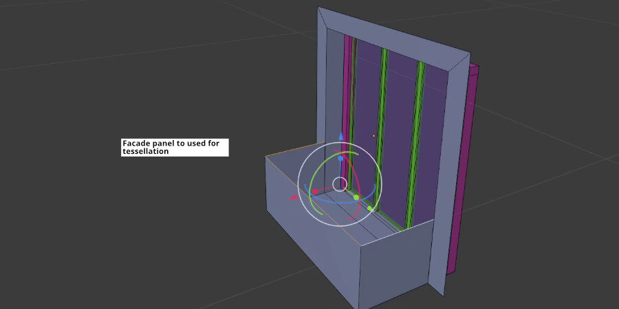
The façade is composed of a simple panel tessellated over the subdivided mesh. It is best to separate the façade panels from the rest of the object, preferably in a duplicate. Within Tissue’s settings there is the option to apply the tessellation to a specific part of the mesh, but we will leave that for another time.
Once the façade base mesh has been separated, create a simple panel, starting from the lovely 2m x 2m plane rotated vertically, inset, extruded inwards, inset again for the frame, subdivided intro three sliding doors, and with a balcony.
If you have not used Tissue before then I suggest watching this video for a more detailed guied. Tissue is an addon bundled with Blender, and it need to be enabled first in the preferences. Once enabled, select the base mesh first, and then the panel and click “tessellate”. A popup will show up, press OK for now.

Chances are that the panels are not rotated correctly, so we will need to UV unwrap the base mesh. Yes, the base mesh instead of the tessellation object. Select the base mesh, go into edit mode, go to the UV menu, and select cube projection with everything unwrapped.
Now select the tessellation object (after writing “tessellation” so many times and autocorrect fixing it, I think I’ve finally learned how to spell it correctly). Go to the object data settings in the properties window (the green icon). Change the rotation from default to UV, and press “refresh.” If the panels are still not correctly aligned, open a UV editor window, select the base mesh again in edit mode, and in the UV editor, rotate everything 90 degrees. Go to the tessellation object, refresh, and repeat in case it’s still not coming in the right way. I am sure there is some sort of logic, I just can’t seem to understand it yet. If you do, please let me know.

Our massing is nearly complete. Add a parapet to the roof, a few roof elements and a base below the last panels, and we are ready to move on to the next step

Context
This is the last bit of modelling. Adjust the size of the plot plane to 50m x 50m. Apply the object scale in object mode. In edit mode, add bevels to the vertices (ctrl+shift+b). Inset 2.5m inwards (i). Add an array, 1 in relative X, 6m in constant X to add a 6m gap. Make the array count 3. Add another array for the Y direction, 1 in relative Y, 6m in constant Y. Adjust the context plots so our building lands in the middle one.
Now, let’s add a few buildings. Once the buildings are added, the two array modifiers can be applied, so to erase the buildings in the middle. Or if you prefer to keep the model more procedural, add a Boolean cube the get rid of the middle plot of the array. Then, duplicate the plot, delete the array modifiers and the context buildings, and move 56m in the X and 56m in the Y directions.

The finished building and context
Cameras, and rendering
We are now in the middle juicy bit in the cake once again. All that cake stuffing proved fruitful! Here we keep things simple and straightforward, as the beauty of cycles takes care of the making the image look good.
Camera
Axonometric views are really fun to do in Blender and relatively easy. Add a camera, adjust the angle of view, go to the camera settings, and change from perspective to orthographic. Adjust the orthographic scale until satisfied. Note that the camera’s location doesn’t matter for the depth of the camera view, but it can accidentally cut through objects as the camera’s near and far points are still the view’s clipping boundaries. I suffered a bit, thinking blender had produced a bug, but my camera was too close to the context objects.

With the camera in place, adjust the context buildings so they don’t block the building in the middle that we will highlight.
Rendering
Switch to cycles, go into render preview mode, add a sun and adjust it with the help of the sun position addon (bundled, needs to be enabled in the preferences). I used the New York preset and adjusted the north offset until satisfied with the shadows. Then, in the world tab, change the background colour to white. Note that we will not use an HDRI as a backdrop here. In the video, I adjusted a series of other setting multiple times. Here are the final settings I used:
Samples 25
Denoising enabled
Image size 1920x1080 scaled to 150%
Filmic look set to very high contrast
Render layers: material index pass enabled

Rendering output and world settings
Materials
Keeping it very vanilla here. However we will create a double vanilla flavour for our building materials. We will also set the material index of the context material to 1, keeping the material index to 0 for all the materials related to the building and the green site. We will be using the mask pass for post processing in Krita, so it is essential to get this right.

Material pass
In the process, I’ve realised that the background is part of the material index set to 0, so I scaled the street plane to beyond the bounds of the camera to make sure that the mask works correctly.
Alternatively, we can set the material index for all budiling materials to 1. I thought it may be easier to set one material index instead of 5, but for future references, we can adjust it.
Did I mention to add a bit of green to the site and the roofs? It’s always nice to have green! Now we are ready to render. F12, please! (that’s the rendering hotkey)
Composting
Once rendered, open a compositor window, enable nodes, add an id mask node, plug it into set alpha node, and into the composite. Save the image. This is our mask. And plug the regular image into the composite and save the image again. This is the base image
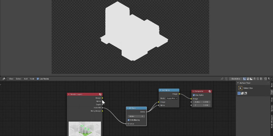
Project mask based on materials index
Post processing
Open the base image in Krita. Drag the mask into Krita, and in the popup, choose to open as new layer. Ctrl+click on the mask layer to enable the selection, add a new filter layer in krita, which is a levels layer by default. Now there is a levels filter layer for the project.
Ctrl+click the mask layer again. In the top menu, go to Selection, invert selection. Add another filter layer. Now we have levels for the context, with both being able to be adjusted independently.

Next, we need to adjust our mask, as due to filmic image exported as 8 bit, it doesn’t come in as white. Deselect all selections. Select the mask layer, go to the filters in the top menu, color, levels. Adjust the highlights to be somewhere near the middle. Now the mask should be completely white. Press apply. There’s no need for this to be an adjustment layer, as it won’t change
Now, right-click on the adjustment layer, and select layer styles. Enable outline. Change the opacity to 100% and adjust the thickness as desired. Once outside of the menu, change the mask layer’s transparency to multiply so we see only the outline without the white.

We are almost done. Let’s add some trees. Make sure you create a new layer. I used a pencil brush for the trunk and a roller brush for the crown. Duplicate the three a few times. Save the image as krita working file and then save as png or jpg.

Final image
What I love about this workflow is that there is manual image tracing, as the mask we’ve set up in Blender does the job for us.
A couple of Krita hints - really fast to improve your workflows!
to deselect a selection, the hotkey combination is ctrl+shift+a instead of ctrl+d
to enable the native file browser when opening and saving files, go to the Settings menu in the header, Configure Krita, then General, miscellaneous tab, and near the bottom, enable the “enable native file dialogues” option, and then hit OK.
Thanks for reading through and stay tuned for another video and another guide showing how we can do a diagram completely in Blender! Yep, without the need of any additional software, so the momement you update something, you have your output there ready and waiting for you.
What are your favourite workflows for producing diagrams?
Patreon
The Blender, Krita, and final images are available on Patreon. I’ve also started producing quick-tip videos on Patreon for expanding specific concepts branching from public youtube videos like the one posted above. Here is an example of the less scripted videos that you can enjoy as a patron.